
1Masonry Chimney & Fireplace
A traditional site-built wood-burning fireplace and brick chimney, shown in side cross-section.
Parts glossary
- Chimney cap
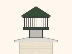
- Metal cover over the flue that keeps out rain, debris, and animals, with mesh that helps arrest sparks.
- Crown
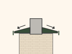
- Concrete or mortar slab on top of the chimney masonry that sheds water away from the flue and brick.
- Flashing (step & counter)
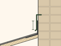
- Sheet-metal pieces sealing the roof–chimney joint: step flashing is woven into the roofing; counter flashing is set into the mortar joints and laps over it.
- Roofline / chimney height above roof*
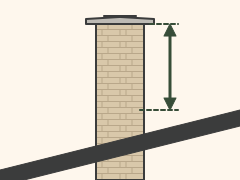
- Where the chimney passes through the roof; the chimney must extend a code-required height above the roof and nearby structures for proper draft and fire safety.
- Brick chimney stack
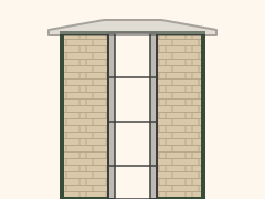
- The masonry walls that enclose and support the flue above the fireplace.
- Flue
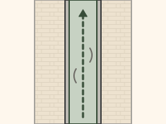
- The open passage that carries smoke and combustion gases up and out.
- Flue liner (clay tile)*
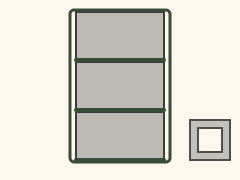
- Clay tile sections lining the flue that protect the masonry from heat and corrosive byproducts and give a smooth path for draft.
- Smoke chamber
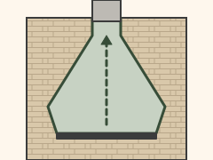
- The tapered space above the throat and smoke shelf that funnels smoke into the flue; its walls should be smooth (parged).
- Damper
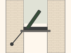
- Movable metal plate at the throat that is opened for a fire and closed when the fireplace is not in use.
- Throat
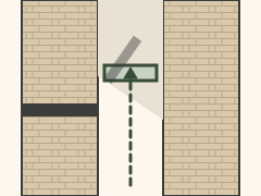
- The narrow opening above the firebox where smoke passes into the smoke chamber; the damper sits here.
- Smoke shelf
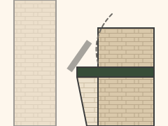
- Horizontal ledge behind the damper that helps turn back downdrafts and catches falling debris.
- Lintel
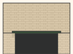
- Steel angle that supports the masonry above the firebox opening.
- Firebox
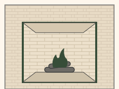
- The chamber where the fire burns.
- Firebrick
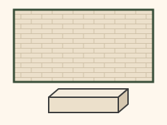
- Heat-resistant (refractory) brick lining the firebox, set in refractory mortar.
- Hearth (inner hearth)
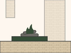
- The noncombustible floor of the firebox.
- Hearth extension*
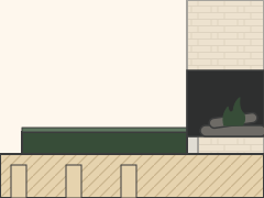
- Noncombustible floor area in front of (and beside) the opening that protects the combustible floor from sparks and embers.
- Ash dump (optional)
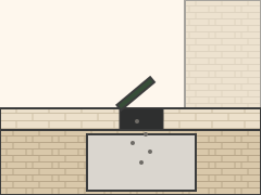
- Small door in the firebox floor, usually near the back wall, that drops ashes into the ash pit.
- Ash pit cleanout door
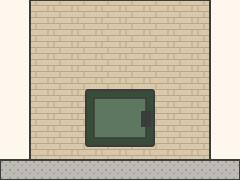
- Metal door at the base of the chimney for removing ashes from the ash pit.
Code clearances & dimensions
From the 2024 IRC as adopted by the 2026 Oregon Residential Specialty Code (construction chapters are mandatory April 1, 2027). During the phase-in, the 2023 ORSC, based on the 2021 IRC, is also permitted. The figures below match both editions except where a row says otherwise. Local amendments can apply, so confirm with the building official.
How to read the clearance drawings
Green arrows and green tags show the minimum distance or thickness from the row next to them. Drawings are not to scale. Rows marked * differ by code edition or opening size, so confirm the edition with the building official.
| Item | Requirement | Code section |
|---|---|---|
| Hearth extension — opening less than 6 sq ft | Not less than 16 inches in front of the opening and not less than 8 in beyond each side. | R1001.10 |
| Hearth extension — opening 6 sq ft or larger | Not less than 20 inches in front of the opening and not less than 12 in beyond each side. | R1001.10 |
| Inner hearth thickness (inside the firebox) | Not less than 4 in. Hearths and hearth extensions shall be concrete or masonry, supported by noncombustible materials, and reinforced to carry their own weight and all imposed loads. Combustible material shall not remain against the underside after construction. | R1001.9, R1001.9.1 |
| Hearth extension thickness (in front of the firebox) | Not less than 2 in. Exception: where the bottom of the firebox opening is raised not less than 8 in above the top of the hearth extension, a hearth extension of not less than ⅜-in-thick brick, concrete, stone, tile, or other approved noncombustible material is permitted. | R1001.9.2 |
| Firebox depth | Not less than 20 in. Exception (Rumford): not less than 12 in and not less than one-third the width of the fireplace opening, with the throat not less than 12 in above the lintel and not less than 1/20 of the cross-sectional area of the fireplace opening. See Rumford fireplaces below. | R1001.6 |
| Firebox wall thickness | 10 in of solid masonry where no lining is provided; or 8 in of solid masonry, including a firebrick or other approved lining not less than 2 in thick. Joints between firebricks not greater than ¼ in. | R1001.5 |
| Fireplace clearance to combustibles | Not less than 2 in from the front faces and sides of masonry fireplaces, and not less than 4 in from the back faces. The airspace shall not be filled, except to provide fireblocking in accordance with R1001.12. The 2024 IRC / 2026 ORSC also allows the airspace to be filled with noncombustible material. | R1001.11 |
| Combustible mantel and trim at the opening | Not within 6 in of a fireplace opening. Combustible material within 12 in of the opening shall not project more than 1/8 in for each 1 in of distance from the opening. | R1001.11 Exception 4 |
| Combustible trim and sheathing at sidewalls and hearth | 2023 ORSC: may abut the masonry if not less than 12 in from the inside surface of the nearest firebox lining. 2026 ORSC / 2024 IRC: not less than 8 in if the opening is less than 6 sq ft; not less than 12 in if the opening is 6 sq ft or larger. | R1001.11 Exception 3 |
| Fireplace fireblocking | Fireplace fireblocking shall comply with R602.8. | R1001.12 |
| Chimney clearance to combustibles | Interior of the building or within the exterior wall: not less than 2 in airspace. Entirely outside the exterior walls, including chimneys that pass through a soffit or cornice: not less than 1 in. The airspace shall not be filled, except to provide fireblocking in accordance with R1003.19. | R1003.18 |
| Chimney — combustibles at masonry or concrete walls | 2023 ORSC: combustible materials shall not be in contact less than 12 in from the inside surface of the nearest flue lining. 2026 ORSC / 2024 IRC: 8 in. | R1003.18 Exception 2 |
| Chimney — combustible trim at side walls | May abut the masonry chimney side walls if not less than 8 in from the inside surface of the nearest flue lining. | R1003.18 Exception 3 |
| Chimney fireblocking | Spaces between chimneys and floors and ceilings through which chimneys pass shall be fireblocked with noncombustible material securely fastened in place. | R1003.19 |
| Chimney termination | Not less than 3 ft above the highest point where the chimney passes through the roof, and not less than 2 ft higher than any portion of a building within 10 ft. | R1003.9 |
| Chimney wall thickness | Solid masonry units, or hollow masonry units grouted solid, with not less than a 4 in nominal thickness. | R1003.10 |
| Clay flue lining — installation and airspace | For fireplaces, clay liners shall extend from the top of the smoke chamber to a point above the enclosing walls, installed in accordance with ASTM C1283, and carried up vertically with a slope not greater than 30° from vertical. Laid in medium-duty water-insoluble refractory mortar (ASTM C199) with tight joints left smooth on the inside. Maintain an airspace or insulation not exceeding the thickness of the flue liner between the liners and the interior face of the chimney masonry. Liners shall be supported on all sides. | R1003.12 |
| Smoke chamber wall thickness | 8 in of solid masonry, with the inside surface parged smooth with refractory mortar (ASTM C199). Where a lining of firebrick not less than 2 in thick, or vitrified clay not less than ⅝ in thick, is provided, the total minimum thickness including the lining shall be 6 in. | R1001.8 |
| Smoke chamber height and slope | Inside height from the throat to the beginning of the flue shall not be greater than the inside width of the fireplace opening. Inside surface not more than 45° from vertical where a prefabricated lining is used or the walls are rolled or sloped; not more than 30° from vertical where the walls are corbeled. | R1001.8.1 |
| Throat location | The throat shall be not less than 8 in above the fireplace opening, and the throat opening shall be not less than 4 in deep. The fireplace throat or damper shall be located not less than 8 in above the lintel. | R1001.6, R1001.7 |
| Damper | A ferrous metal damper, located not less than 8 in above the top of the fireplace opening, installed in the fireplace or the chimney venting it, and operable from the room containing the fireplace. | R1001.7.1 |
| Chimney cricket | Required where the dimension parallel to the ridgeline is greater than 30 in and the chimney does not intersect the ridgeline. Flash and counterflash the intersection. Cricket height H is in Table R1003.20 (12:12 roof: ½ of W; 8:12: ⅓ of W; 6:12: ¼ of W; 4:12: ⅙ of W; 3:12: 1/8 of W). | R1003.20, Table R1003.20 |
| Chimney cap (crown / wash) | A concrete, metal, or stone cap, sloped to shed water, with a drip edge and a caulked bond break around any flue liners, in accordance with ASTM C1283. | R1003.9.1 |
| Chimney cleanout | Provide a cleanout within 6 in of the base of each flue; the upper edge not less than 6 in below the lowest chimney inlet opening; opening height not less than 6 in; noncombustible cover. Exception: not required for flues serving masonry fireplaces where cleaning is possible through the fireplace opening. | R1003.17 |
| Ash dump cleanout (where provided) | Ferrous metal or masonry doors and frames constructed to remain tightly closed except when in use, located so that ash removal will not create a hazard to combustible materials. | R1001.2.1 |
| Flue size relative to the fireplace opening | Option 1: round flues not less than 1/12 of the fireplace opening area; square flues, and rectangular flues with an aspect ratio less than 2 to 1, not less than 1/10; rectangular flues with an aspect ratio of 2 to 1 or more, not less than 1/8. Option 2: size the flue in accordance with Figure R1003.15.2, using chimney height measured from the firebox floor to the top of the flue. | R1003.15, R1003.15.1, R1003.15.2 |
| Spark arrestor (Oregon) | On forest-zoned lands, each chimney shall have a spark arrestor (ORS 215.730). Where a spark arrestor is installed, it shall meet R1003.9.2, including a net free area not less than four times the net free area of the flue outlet. | Ch. 10 note, R1003.9.2 |
Rumford fireplaces
A Rumford is a style of masonry fireplace with a tall opening, a shallow firebox, widely splayed side walls (covings), a back wall that is straight or rolls forward near the top, and a rounded “breast” that streamlines the throat. Count Rumford described the design in essays published in 1796 and 1798. Jim Buckley of Buckley Rumford describes Rumfords as “tall and shallow to reflect more heat,” with “streamlined throats to eliminate turbulence and carry away the smoke with little loss of heated room air.”
Simplified and not to scale. The Rumford panels follow the shape of a typical 36 in Buckley Rumford; the standard panels use the 20 in code depth. Green tags show code minimums.
How it works
- The shallow firebox and wide covings put more of the fire in view of the room, so more radiant heat goes out through the opening instead of up the chimney.
- The rounded breast lets room air and smoke flow smoothly up through a narrow throat instead of tumbling over a sharp lintel. Buckley reports Rumford openings can be built almost a foot taller than regular fireplaces with throats less than half the size.
- Glass doors block much of the radiant heat; Buckley puts it at about 80% of the infrared radiation.
What the code says
The IRC, as adopted in Oregon, allows a Rumford as an exception to the 20 in firebox depth: the depth must be not less than 12 in and not less than one-third of the width of the fireplace opening, and the throat must be not less than 12 in above the lintel and not less than 1/20 of the cross-sectional area of the fireplace opening (R1001.6 Exception; see the firebox depth row). Every other masonry fireplace rule in the table above still applies, including the hearth, hearth extension, firebox walls, smoke chamber, damper, flue sizing, and clearances to combustibles. Because Rumford openings are tall, many are 6 sq ft or larger, which calls for the larger hearth extension (20 in in front and 12 in beyond each side).
Typical Rumford proportions (design guidance, not code) *
- The back wall (fireback) is about as wide as the firebox is deep, and the opening is about three times that width, so the depth and the fireback are each about one-third of the opening width.*
- The covings are flat and set at about 135° to the fireback (about 45° to the face of the opening).*
- Many Rumfords have a back wall that rises straight for a short distance and then rolls forward near the top toward the throat, as in the drawing above. Buckley’s original design keeps the back wall straight and vertical all the way up to the throat. Both are built in practice.*
- The throat is narrow. Buckley’s instructions call for a masonry throat opening of 4 in front to back for a 36 in Rumford, 4½ in for 42 in, and 5 in for 48 in.*
- Example: the Buckley R36 certified core is 36 in wide, 32½ in tall, and 14 in deep, with a 13½ in fireback and 18 in covings.*
* These are design proportions from the sources below, not code requirements. Verify with the code reference and with the fireplace designer or component manufacturer.
What to check on an inspection
- Throat: the rounded breast is intact, throat tiles or parging are not cracked or displaced, and the narrow throat is not blocked by debris or creosote.
- Smoke chamber: walls smooth and sound, without open joints, cracks, or heavy deposits. Many newer Rumfords use clay smoke chamber and throat components.
- Damper type and operation: a Rumford throat damper at the throat, or a top-sealing damper at the top of the flue that is operated from the room. Either way, the code requires a ferrous metal damper operable from the room (R1001.7.1).
- Firebox: firebrick and refractory mortar joints in good condition, and the depth and opening fit the R1001.6 exception if the fireplace was built shallower than 20 in.
- Hearth extension and clearances: the same masonry rules as any other fireplace (see the table above), keeping in mind that a tall opening often means an opening of 6 sq ft or more.
Sources: Buckley Rumford, What is a Rumford Fireplace, Anyway? and Rumford: The Fireplace That’s More Like It Used To Be (Jim Buckley); Buckley Rumford building instructions (throat opening depths) and certified core specifications (R36 dimensions and damper); Fine Homebuilding, Rumfordizing Brick by Brick (depth and fireback each one-third of the opening width; covings at 45° to the opening); IRC R1001.6 and R1001.7.1, as adopted in the Oregon Residential Specialty Code.
Verify with code *
- Hearth extension size
- Clearances to combustibles
- Flue liner sizing
- Chimney height above the roof
Verify with the Oregon Residential Specialty Code, IRC R1001–R1003, and NFPA 211.